
Notes
|
Topics to be learn :
|
Introduction :
Light: It is a form of electromagnetic radiation (radiant energy) which produces in us the sensation of vision.
Important uses of light:
- Light enables us to see the objects in the beautiful and colourful world around us.
- Light is highly useful in modern communication. We can transmit thousands of telephonic conversations simultaneously via optical fibres over long distances.
Ray of light: The direction or path along which light energy travels in a medium is called a ray of light. It is represented by a straight line with an arrow marked on it.
Beam of light: A group of light rays is called a beam of light.
Types of beams of light: A beam of light may be parallel, convergent or divergent, as shown in Fig.
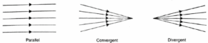
- The rays from a distant light source (such as the sun) are parallel to each other, they constitute a parallel beam.
- In a convergent beam, the rays proceed towards a point.
- In a divergent beam, the rays proceed away from a point.
Electromagnetic waves: An electromagnetic wave is a wave constituted by oscillating electric and magnetic fields which oscillate in mutually perpendicular directions and also perpendicular to the direction of propagation of the wave.
Electromagnetic nature of light waves: According to Maxwell, light travels through space in the form of electromagnetic waves. The wavelength range of visible light is 4x 10⁷ m to 8 x 10⁷ m.
Reflection, refraction and absorption of light: When light travelling through
one medium falls on the surface of another medium, the following three effects may occur at the surface of separation of the two media:
- A part of the incident light is turned back into the first medium. This is called reflection of light. Reflection of light occurs when light falls on a highly polished surface.
- Another part of incident light is transmitted into the second medium and bends from its path at the surface of separation. This is called refraction of light. Refraction of light occurs when light falls on a transparent medium.
- The remaining part of incident light is absorbed at the surface of separation. This is called absorption of light.
Optical image: When a beam of rays starting from a point source of light suffers a change in direction due to reflection or refraction, and the reflected or refracted rays actually converge or appear to diverge from another point, then the second point is called the image of the first point.
Real image: If a beam of rays starting from a point source of light, after reflection or refraction, actually converges to a point, then the second point is called the real image of the first.
- A real image is formed due to actual intersection of rays, so it can be obtained on a screen.
- It is usually inverted.
- The images formed on a cinema screen are real images.
Virtual image: If a beam of rays starting from a point source of light, after reflection or refraction, appears to diverge from another point, then the second point is called the virtual image of the first.
- A virtual image is not formed due to the actual intersection of the rays, so it cannot be obtained on a screen.
- It is usually erect.
- The image of our face in a looking glass is a virtual image.
Reflection of light :
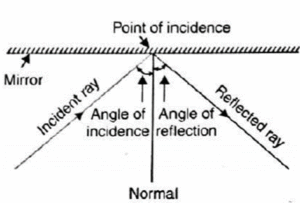
- Incident ray: The ray of light that falls on the reflecting surface is called incident ray.
- Reflected ray: The ray that goes away from the reflecting surface after reflection from it is called reflected ray.
- Point of incidence: The point at which the incident ray strikes the reflecting surface is called point of incidence.
- Normal: The line drawn perpendicular to the reflecting surface at the point of incidence is called the normal at that point.
- Angle of incidence: It is the angle between the incident ray and the normal to the reflecting surface at the point of incidence. It is denoted by i.
- Angle of reflection: It is the angle between the reflected ray and the normal to the reflecting surface at the point of incidence. It is denoted by r.
Mirror: A highly polished surface which is smooth enough to reflect a good fraction of light incident on it is called a mirror. The mirror may be a highly polished metal surface or an ordinary glass plate coated with a thin silver layer.
Laws of reflection of light at a plane mirror :
As shown in Fig., when a ray of light is incident on a mirror, it gets reflected in accordance with the following laws of reflection:
- First law: The incident ray, the reflected ray and the normal at the point of incidence all lie in the same lane.
- Second law: The angle of incidence (i) is equal to the angle of reflection (r) i.e., ∠ i = ∠ r
These laws of reflection are valid for both plane and curved surfaces.
Properties of images formed by a plane mirror:
- The image formed by a plane mirror is virtual and erect.
- It is of the same size as the object.
- The image is formed as far behind the mirror as the object is in front of it i.e. u= v.
- It is laterally inverted i.e., image is inverted sideways with respect to the object.
- The number of images of an object held between two plane parallel mirrors are infinity.
- When a person moves towards a mirror, his virtual image also moves towards the mirror by equal distance.
- If mirror is turned, the reflected ray turns through twice the angle through which the plane mirror is turned.
Lateral inversion: If we stand before a plane mirror and move our right hand, our image appears to move its left hand. In fact, our entire image is reversed sideways. This sideways reversal of the image is known as lateral inversion.
Cause of lateral inversion:
- Lateral inversion is due to the fact that in a plane mirror the image is as far behind the mirror as the object is in front of it and that the front of the image and the front of the object face each other.
- The images of symmetrical letters like A, H, I, M, O, T, U, V, W, X, Y, 8 are not affected by lateral inversion.
- The laterally inverted image of the word HUNDRED is as shown in Fig.

Spherical mirrors :
Spherical mirror: A spherical mirror is a mirror whose reflecting surface is a
part of a hollow sphere. Spherical mirrors are of two types:
- Concave mirror: A spherical mirror is concave if it is silvered on the outer bulged surface and reflects light from the inner hollow surface.
- Convex mirror: A spherical mirror is convex if it is silvered on the inner hollow surface and reflects light from the outer bulged surface.
Structure and characteristics of spherical mirrors:
In below Fig. let APB be a principal section of a spherical mirror, i.e., the section cut by a plane passing through pole and centre of curvature of the mirror.
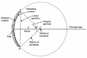
- Pole: It is the middle point P of the spherical mirror.
- Centre of curvature: It is the centre C of the sphere of which the mirror forms a part.
- Radius of curvature: It is the radius R (= AC or BC) of the sphere of which the mirror forms a part.
- Principal axis: The line passing through the pole and the centre of curvature of mirror is called its principal axis.
- Linear aperture: It is the diameter AB of the circular boundary of the spherical mirror.
- Angular aperture: It is the angle ACB subtended by the boundary of the spherical mirror at its centre of curvature.
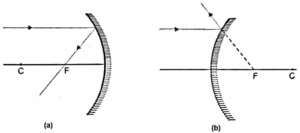
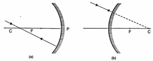
- Principal focus: It is a point F on the principal axis where a beam of light parallel to the principal axis either actually converges to or appears to diverge from, after reflection from a mirror.
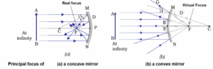
- Converging mirror : As shown in Fig.(a), when a beam of light is incident on a concave mirror parallel to its principal axis, it actually converges to a point F on the principal axis. So a concave mirror has a real focus and it is called a converging mirror also.
- Diverging mirror : As shown in Fig. (b), when a beam of light is incident on a convex mirror parallel to its principal axis, after reflection it appears to diverge from a point F (lying behind the mirror) on the principal axis. So a convex mirror has a virtual focus and it is called a diverging mirror also.
- Focal length : It is the distance f (= PF) between the focus and the pole of the
- Focal plane : The vertical plane passing through the principal focus and perpendicular to the principal axis is called focal plane. When a parallel beam of light is incident on a concave mirror at a small angle to the principal axis, it is converged to a point in the focal plane of the mirror.
Concave Mirror :
Relation between focal length (f) and radius of curvature (R) for a concave mirror :
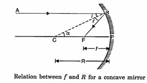
Consider a ray AB parallel to the principal axis and incident at the point B of a concave mirror as shown in Fig.
After reflection from the mirror, this ray passes through its focus F, obeying the laws of reflection.
If C is the cente of curvature, then CP = R, is the radius of curvature and CB is normal to the mirror at point B.
According to the law of reflection,
∠ i = ∠ r
As AB is parallel to CP, so
∠ α = ∠ i (Alternate angles)
∴ ∠ α = ∠ r
Thus Δ BCF is isosceles. Hence CF = FB.
If the aperture (or size) of the mirror is small, then B lies close to P, so that,
FB ≈ FP
FP = CF = \(\frac{1}{2}\)CP
Or, f = \(\frac{R}{2}\)
Or, Focal length = \(\frac{1}{2}\)x Radius of curvature.
Thus, the principal focus of a spherical mirror lies midway between the pole and the centre of curvature.
Therefore, the principal focus of concave mirror is a point on its principal axis at which a 'beam of light parallel to the principal axis actually converges after reflection from the mirror.
Image Formation by Spherical Mirrors :
Nature, size and position of images formed by a concave mirror for different positions of the object :
The nature, position, and size of the image formed by a concave mirror depends on the position of the object in relation to points P, F and C.
Representation of Images Formed by Spherical Mirrors Using Ray Diagrams :
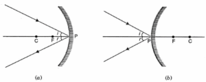
Rules for drawing images formed by spherical mirrors: The position of the image formed by spherical mirrors can be found by considering any two of the following rays of light coming from a point on the object.
(i) A ray proceeding parallel to the principal axis will, after reflection, pass through the principal focus in the case of a concave mirrors [Fig. (a)], and appear to come from focus in the case of a convex mirror [Fig. (b))
(ii) A ray passing through the principal focus in the case of a concave mirror [Fig.(a)], and directed towards the principal focus in the case of a convex mirror will [Fig. (b)], after reflection, become parallel to the principal axis.
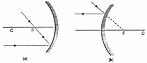
(iii) A ray passing through the centre of curvature in the case of a concave mirror [Fig.(a)], and directed towards the centre of curvature in the case of a convex mirror [Fig.(b)] falls normally (∠ i = ∠ r = 0°) and is reflected back along the same path.
(iv) A ray incident obliquely to the principal axis, towards the pole P, on the concave mirror [Fig.(a)] or a convex mirror [(b)] is reflected obliquely, following the laws of reflection at the point of incidence, i.e., the incident and reflected rays make equal angles with the principal axis.
Explanation of formation of images by a concave mirror for different positions of the object :
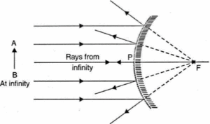
(i) Object at infinity: When the object lies at infinity, the rays from the distant object fall on the concave mirror as a parallel beam, as shown in below Fig.
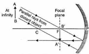
- The ray passing through F becomes parallel to the principal axis after reflection from the mirror. The ray through C is reflected back along its own path.
- The two reflected rays meet at point A’ in the focal plane.
- Hence a real, inverted and highly diminished image A'B’ is formed at the focus F of the concave mirror.
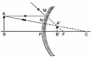
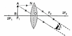
(ii) Object beyond the centre of curvature :
In Fig. an object AB is placed on the principal axis of a concave mirror and beyond its centre of curvature C.
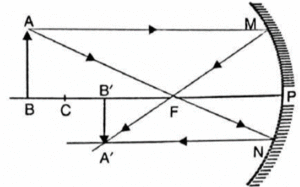
- A ray AM going parallel to the principal axis passes, after reflection, through the principal focus F. Another ray AN passing through F becomes, after reflection, parallel to the principal axis.
- The two reflected rays meet at point A’. Thus A’ is the image of A.
- If we draw A’B’ perpendicular to the principal axis, then A’B’ is the complete image of object AB.
- Hence, the image is real, inverted, diminished in size and is formed between the focus and the centre of curvature.
(iii) Object at the centre of curvature:
In Fig. an object AB is placed at the centre of curvature C of a concave mirror.
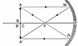
- A ray AM parallel to the principal axis passes after reflection through the focus F. Another ray AN passing through F becomes after reflection, parallel to the principal axis.
- The two reflected rays meet at point A’. Thus A’ is the image of point A.
- The perpendicular A’B’ drawn on the principal axis coincides with the position of AB.
- Hence a real, inverted and of same size image is formed at the centre of curvature.
(iv) Object between principal focus and centre of curvature:
In Fig. an object AB is placed between the focus F and centre of curvature C of a concave mirror.
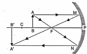
- A ray AM parallel to the principal axis passes, after reflection, through the focus F.
- Another ray AN passing through F becomes, after reflection, parallel to the principal axis.
- The two reflected rays meet at point A’. The line A’B’ drawn perpendicular to principal axis is the complete image of AB.
- Hence a real, inverted and enlarged image is formed beyond the centre of curvature.
(v) Object at the principal focus:
In Fig. an object AB is placed at the principal focus F of a concave mirror.
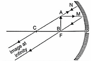
- A ray AM parallel to the principal axis passes, after reflection, through the focus F.
- Another ray AN coming through C falls normally on the mirror and reflects its path after reflection.
- The two reflected rays are parallel to each other and meet at infinity.
- Hence a real, inverted and highly enlarged (or magnified) image is formed at infinity.
(vi) Object between the principal focus and pole:
In Fig. an object AB is placed between the focus F and the pole P of a concave mirror.
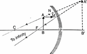
- A ray AM parallel to the principal axis passes, after reflection, through the focus.
- Another ray AN coming from C follows its path back. Both the reflected rays appear to diverge from a common point A’ behind the mirror.
- So A’ is the virtual image of A. The normal A’B’ upon the principal axis is the complete image of AB.
- Hence a virtual, erect and magnified image is formed behind. the mirror.
Uses of concave mirrors :
- Shaving mirror: A concave mirror is used as a shaving or make-up mirror because it creates a more upright and magnified picture of the face when held closer to the face.
- As head mirror: E.N.T. specialists employ a concave mirror on their forehead as a head mirror. The light from a lamp, following reflection in a mirror, is focused into the patient's throat, ear, or nose, making the afflicted area more apparent.
- In ophthalmoscope: An ophthalmoscope is a concave mirror with a small hole in the centre. The doctor looks through the hole from behind the mirror, while a beam of light reflected from the mirror is directed into the pupil of the patient's eye, revealing the retina.
- In headlights: Concave mirrors are used as reflectors in headlights of motor vehicles, railway engines, torch lights, etc. The source is placed at the focus of the concave mirror. The light rays after reflection travel over a large distance as a parallel beam of high intensity,
- In astronomical telescopes: A concave mirror of large diameter (5 m or more) is used as objective in an astronomical telescope. It collects light from the sky and makes visible even those faint stars which cannot be seen with naked eye.
- In solar furnaces: Large concave mirrors are used to concentrate sunlight to produce heat in solar furnace.
Formation of image by a convex mirror:
(i) Object between pole and infinity:
In Fig. an object AB is placed on the principal axis of a convex mirror.
- A ray AM parallel to the principal axis appears to come, after reflection, from the focus F.
- The ray AN going towards C is reflected back along its own path. The two reflected rays appear to come from a common point A’ behind the mirror.
- So A’ is the virtual image of A. The normal A’B’ upon the principal axis is the complete image of AB.
- Hence a virtual, erect and diminished image is formed behind the mirror between F and P.
(ii) Object at infinity:
When the object is placed at infinity, the incident parallel rays appear to diverge from the focus after reflection from the mirror, as shown in Fig.
- Hence a virtual, erect and extremely diminished image is formed behind the mirror.
Know This :
|
Properties of the image formed by a convex mirror:
- The image is always virtual and erect.
- The image is highly diminished or point sized.
- It is always formed between F and P.
- As the object is moved towards the pole of a convex mirror, image also moves towards its pole and gradually increases in size till its size becomes almost equal to that of the object.
Uses of convex mirrors:
Rear-view mirror in automobiles : Drivers use convex mirror as a rear-view mirror in automobiles because of the following two reasons:
- A convex mirror always forms an erect, virtual and diminished image of an object placed anywhere in front of it.
- A convex mirror has a wider field of view than a plane mirror of the same size.
- Thus convex mirrors enable the driver to view much larger traffic behind him than would be possible with a plane mirror.
- The main disadvantage of a convex mirror is that it does not give the correct distance and the speed of the vehicle approaching from behind.
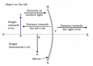
Sign Convention for Reflection by Spherical Mirrors :
New cartesian sign convention for reflection by spherical mirrors: According to this convention:
- The object is always placed to the left of the mirror. This implies that the light from the object falls on the mirror from the left-hand side.
- All the distances parallel to the principal axis are measured from the pole of the mirror.
- All distances measured in the direction of incident light are taken as positive.
- All distances measured in the opposite direction of incident light are taken as
- Heights measured upwards and perpendicular to the principal axis are taken positive.
- Heights measured downwards and perpendicular to the principal axis are taken negative.
Mirror Formula and Magnification :
Mirror formula: The mirror formula is a mathematical relation between the object distance u, image distance v and focal length f of a spherical mirror. This relation is \(\frac{1}{u}+\frac{1}{v}=\frac{1}{f}\)
where, u = object distance, v = Image distance , f = Focal length
This formula is applicable to all concave and convex mirrors.
Linear magnification: The ratio of the height of the image to that of the object is called linear magnification or transverse magnification or just magnification. It is denoted by m.
m = \(\frac{\text{height of image}}{\text{height of object}}+\frac{h'}{h}=-\frac{v}{u}\)
The magnification m is also related to the object distance (u) and image distance (v).
Linear magnification in terms of u and f : From mirror formula, we have
\(\frac{1}{v}=\frac{1}{f}-\frac{1}{u}\) = \(\frac{u-f}{uf}\) or \(\frac{u}{v}\) = \(\frac{u-f}{f}\)
∴ m = \(-\frac{v}{u}\) = \(\frac{u}{f-u}\)
Linear magnification in terms of v and f : From mirror formula, we have
\(\frac{1}{u}=\frac{1}{f}-\frac{1}{v}\) = \(\frac{v-f}{vf}\) or \(\frac{v}{u}\) = \(\frac{v-f}{f}\)
∴ m = \(-\frac{v}{u}\) = \(\frac{f-v}{f}\)
Hence, for any spherical mirror, concave or convex, we have
m = \(-\frac{v}{u}\) = \(\frac{u}{f-u}\) = \(\frac{f-v}{f}\)
- For concave mirror |m| ≥ 1 or |m| < 1 i.e. Image may be real or virtual.
- For convex mirror |m| < 1 i.e. Image is virtual.
- If |m| > 1, the image is magnified.
- If |m| < 1, the image is diminished.
- If |m| = 1, the image is of the same size as the object.
- If m is positive, the image is virtual and erect.
- If m is negative, the image is real and inverted.
Refraction of light
Refraction of light: The phenomenon of bending of light from its straight line path as it passes obliquely from one transparent medium to another is called refraction of light.
- The path of the ray of light in the first medium is called incident ray.
- The path of the ray of light in the second medium is called refracted ray.
- The angle between the incident ray and the normal at the surface of separation is called angle of incidence (i).
- The angle between the refracted ray and the normal at the surface of separation is called angle of refraction (r).
Whenever a ray of light passes from one medium to another, the following three situations are possible:
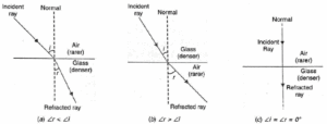
- When a ray of light passes from an optically rarer medium to a denser medium, it bends towards the normal and ∠ r < ∠ i, as shown in Fig.(a).
- When a ray of light passes from an optically denser to a rarer medium, it bends away from the normal and ∠ r > ∠ i, as shown in Fig.(b).
- A ray of light travelling along the normal passes undeflected. Here ∠ i = ∠ r = 0°.
Examples of refraction of light:
(i) When a pencil is partly immersed in water in a glass tumbler, it appears to be displaced at the interface of air and water.
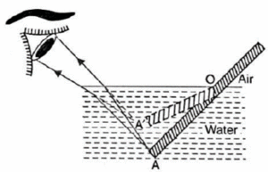
- As shown in Fig. rays starting from point A in the optically denser medium bend away from normal after passing through water-air interface
- On entering the eye, the ray appears to come from A’. Point A appears to be at A’ and the portion AO appears to be at OA’.
- Thus the light reaching our eye from the portion of the pencil inside water appears to come from different direction, compared to the part above water. That is why the pencil appears bent at the interface.
- If instead of water, we use liquids like kerosene or tarpentine, the pencil will appear to be displaced or bent by a different extent.
(ii) If we see a water tank, its bottom appears to be raised. It also appears to be concave shaped although it is flat.
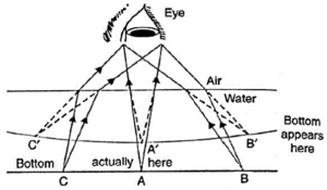
- Rays from A (Fig.) after striking water-air interface bend away from normal. Thus point A appears to be at A i.e., the bottom appears to be raised and concave.
- For the same reason, when a thick glass slab is placed over some printed matter, its letters appear raised when seen through the slab.
Refraction of light through a rectangular glass slab :
- In the figure, EO is the incident ray, OO’ is the refracted ray and O’H is the emergent
- We observe that the emergent ray O’H is parallel to the incident ray EO. This is because the extent of bending of the ray of light at the face AB is equal and opposite to that at face CD.
- However, the emergent ray is shifted sideward slightly by a perpendicular distance OL with respect to the incident ray.
- This lateral shift in the path of light on emerging from a medium with parallel faces is called lateral displacement.
Laws of refraction of light:
The following are the laws of refraction of light.
(i) The incident ray, the refracted ray and the normal to the interface of two transparent media at the point of incidence, all lie in the same plane.
(ii) The ratio of sine of angle of incidence to the sine of angle of refraction is a constant, for the light of a given colour and for the given pair of media.
If i is the angle of incidence and r is the angle of refraction, then, \(\frac{sin\,i}{sin\,r}\) = n21 (constant)
- This constant n21 value is called the refractive index of the second medium with respect to the first.
- This law is also known as Snell’s law of refraction. (This is true for angle 0 < i < 90o).
- The same laws of refraction are valid for the plane as well as spherical refracting surfaces.
The Refractive Index :
Refractive index: The refractive index of a medium for a light of given wavelength may be defined as the ratio of the speed of light in vacuum to its speed in that medium.
n = \(\frac{\text{speed of light in vacuum (c)}}{\text{speed of light in medium (v)}}\)
The refractive index of a medium with respect to vacuum is also called its absolute refractive index.
Cause of refraction of light: Light travels with different speeds in different media. The bending or refraction of light occurs due to the change in the speed of light as it passes from one medium to another medium. Using Snell’s law of refraction, we can write
n = \(\frac{sin\,i}{sin\,r}\) = \(\frac{c}{v}\)
As the speed of light (c) in vacuum is greater than the speed of light (v) in any medium or c > v, so sin I > sin r or ∠ i > ∠ r. That is why, a ray of light bends towards the normal as it passes from a rarer medium (air) to a denser medium (glass).
Physical significance of refractive index :
The refractive index of any medium gives the ratio of the speed of light in vacuum to the speed of light in that medium.
- For example, the refractive index of water, nw = 1.33. This means that the ratio of the speed of light in vacuum or air to the speed of light in water is 1.33.
Optical density :
- The optical density of a medium represents its ability to refract light.
- A medium having larger refractive index is called optically denser medium than the other.
- A medium having lower refractive index is called optically rarer medium.
- The speed of light is higher in a rarer medium than a denser medium.
- Thus, a ray of light travelling from a rarer medium to a denser medium slows down and bends towards the normal.
- When it travels from a denser medium to a rarer medium, it speeds up and bends away from the normal.
Refractive indices of some material media (with respect to vacuum) :
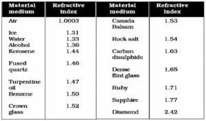
- The refractive index of rock salt is 1.54. It indicates that the ratio of the speed of light in vacuum to that in rock salt is 1.54.
- Absolute refractive index of a medium can’t exceed unity, because speed of light is maximum in vacuum.
- Refractive index is minimum for vacuum (n = 1).
- Refractive index is maximum for diamond (n = 2.42).
- Optically denser medium may not possess greater mass density than an optically rarer medium. For example, kerosene/turpentine oil, having higher refractive index, is optically denser than water, although its mass density is less (as oil floats on the surface of water) than that of water.
Relative refractive index: The relative refractive index of medium 2 with respect
to medium 1 is defined as the ratio of speed of light (v1) in medium 1 to the speed of light (v2) in medium 2 and is denoted by n21. Thus
n21 = \(\frac{\text{speed of light in first medium}}{\text{speed of light in second medium}}\) = \(\frac{v_1}{v_2}\)
Similarly, the refractive index of medium 1 with respect to medium 2 is denoted by n12. It is given by
n12 = \(\frac{\text{speed of light in second medium}}{\text{speed of light in first medium}}\) = \(\frac{v_2}{v_1}\)
- Light speeds up when it goes from a medium of higher refractive index to lower refractive index, say from crown glass to water.
- Light slows down when it goes from a medium of lower refractive index to higher refractive index, say from water to diamond.
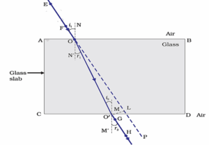
A ray of light suffers two refractions, when it passes through a glass slab :
Explanation :
Consider a rectangular glass slab PQRS, as shown in Fig.
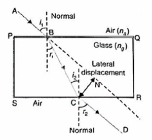
- A ray AB is incident on the face PQ at an angle of incidence i1.
- On entering the glass slab, it bends towards the normal and travels along BC at an angle of refraction r1.
- The refracted ray BC is incident on the face SR at an angle of incidence i2.
- The emergent ray CD bends away from the normal at an angle of refraction r2
Using Snell’s law for refraction from air to glass at face PQ,
\(\frac{sin\,i_1}{sin\,r_1}\) = \(\frac{n_g}{n_a}\) ….(1)
Using Snell’s law for refraction from glass to air at face SR,
\(\frac{sin\,i_2}{sin\,r_2}\) = \(\frac{n_a}{n_g}\)
But i2 = r1
∴ \(\frac{sin\,r_1}{sin\,r_2}\) = \(\frac{n_a}{n_g}\) ….(2)
Multiplying equations (1) and (2), we get
\(\frac{sin\,i_1}{sin\,r_1}\) x \(\frac{sin\,r_1}{sin\,r_2}\) = \(\frac{n_a}{n_g}\) x \(\frac{n_a}{n_g}\) = 1
Or, sin i1 = sin r2 or i1 = r2
Thus, the emergent ray CD is parallel to the incident ray AB, but it has been laterally displaced by a perpendicular distance CN with respect to the incident ray.
- This lateral shift in the path of light on emerging from a medium with parallel faces is called lateral displacement.
- It is found that the lateral displacement is directly proportional to the thickness of the glass slab.
Lateral displacement depends on :
- Angle of incidence : For i = 0°, lateral shift is zero.
- Thickness of the glass slab : Lateral displacement will increase with the increase in thickness of the glass slab.
- Refractive index of the slab material.
Q. Explain why a tank appears shallower.
Answer :
Apparent depth is smaller than real depth: It is due to refraction of light that a water tank appears shallower or an object placed at its bottom appears to be raised.
Explanation :
Below Figure shows a point object placed at the bottom of a beaker filled with water.
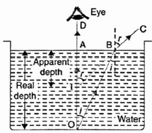
- The rays OA and OB starting from O are refracted along AD and BC, respectively. These rays appear to diverge from point I. Thus, I is the virtual image of O. Clearly, the apparent depth Al is smaller than the real depth AO.
- That is why water tank appears shallower or an object (coin) placed at the bottom appears to be raised.
It is found that the refractive index of denser medium,
n = \(\frac{Real\,depth}{Apparent\,depth}\)
Lenses :
Lens: A lens is a piece of a refracting medium bounded by two surfaces, at least
one of which is a curved surface. The commonly used lenses are the spherical lenses, which have either both surfaces spherical or one spherical and the other a plane one.
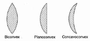
Spherical lenses are of two main types:
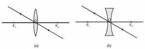
(i) Convex or converging lens: It is thicker at the centre than at the edges. It converges a parallel beam of light on refraction through it. It has a real focus.
Types of convex lenses:
- Double convex or biconvex lens: Both the surfaces are convex. It is simply called a convex lens.
- Planoconvex lens: One surface is convex and the other is plane.
- Concavoconvex: One surface is convex and the other is concave.
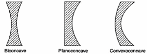
Concave or diverging lens: It is thinner at the centre than at the edges. It diverges a beam of light on refraction through it. It has a virtual focus.
Types of concave lenses:
- Double concave or biconcave lens: Both the surfaces are concave. It is simply called a concave lens.
- Planoconcave lens: One surface is concave and the other is plane.
- Convexoconcave: One surface is concave and the other is convex.
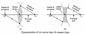
Terms used in connection with spherical lenses:
(i) Centre of curvature (C): The centre of curvature of the surface of a lens is the centre of the sphere of which it forms a part. Because a lens has two surfaces, so it has two centres of curvature (C1, C2).
(ii) Radius of curvature (R): The radius of curvature of the surface of a lens is the radius of the sphere of which the surface forms a part.
(iii) Principal axis (C1, C2): It is the line passing through the centres of curvature of the lens.
(iv) Principal focus (F): A narrow beam of light parallel to the principal axis either converges to a point or appears to diverge from a point on the principal axis after refraction through the lens. This point is called principal focus. All lenses have two principal focii.
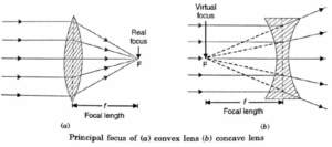
(v) Optical centre (O): It is a point situated within the lens through which a ray of light passes undeviated.
(vi) Focal length (f): It is the distance between the principal focus and the optical centre of the lens.
(vii) Aperture: It is the diameter of the circular boundary of the lens.
Type of lens with which paper can be burnt :
- When a high intense parallel beam of light falls on a convex lens, it converges and meets at the focus on the other side of the lens. If a piece of paper is placed at F, it gets burnt, because of concentration of large amount of sunlight.
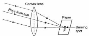
- The same action cannot be done with the help of a concave lens, because concave lens is a diverging lens. Instead of bringing rays to one point after refraction, it diverges them and there is no concentration of light at one point.
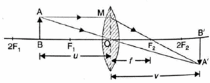
Image Formation by Lenses :
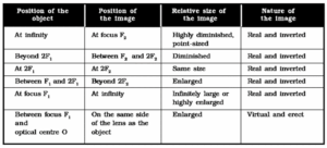
Convex Lens :The nature, position and size of the image formed by a convex lens depends on the position of the object in relation to points O, F1 and 2F1,.
Nature, position and relative size of the image formed by a convex lens for various positions of the object :
Nature, position and relative size of the image formed by a concave lens for various positions of the object :
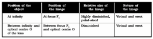
Image Formation in Lenses Using Ray Diagrams :
Rules used for drawing images formed by spherical lenses :
The position of the image formed by any spherical lens can be found by considering any two of the following rays of light coming from a point on the object:
(i) A ray from the object parallel to the principal axis after refraction passes through
the second principal focus F2 [in a convex lens, as shown in Fig. (a) or appears to diverge [in a concave lens, as shown in Fig. (b)] from the first principal focus F1.
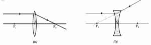
(ii) A ray of light passing through the first principal focus [in a convex lens, as shown in Fig. (a)] or appearing to meet at it [in a concave lens, as shown in Fig. (b)] emerges parallel to the principal axis after refraction.
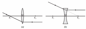
(iii) A ray of light, passing through the optical centre of the lens, emerges without any deviation after refraction, as shown in Fig. (a) and (b).
Ray diagrams : Image formation by a convex lens -
The following are the positions and nature of images formed by a convex lens for different positions of the object:
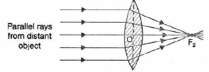
(i) Object at infinity: The image formed is at focus, real, inverted and highly diminished, as shown in Fig.
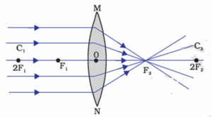
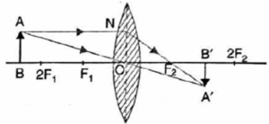
(ii) Object beyond 2F1: The image formed is between F2 and 2F2 on the other side of the lens, real, inverted and diminished, as shown in Fig.
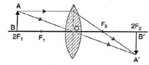
(iii) Object at 2F1: The image formed is at 2F2, real, inverted and of same size as that of the object, as shown in Fig.
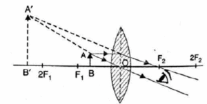
(iv) Object between F1 and 2F1: The image formed is beyond 2F2 real, inverted and magnified, as shown in Fig.
(v) Object at F1: The image formed is real, inverted, highly enlarged and at infinity, as shown in Fig.
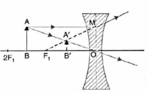
Ray diagrams : Image formation by a concave lens -
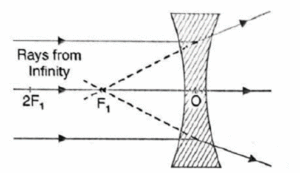
(i) Object at infinity: The rays from an object at infinity are parallel to each other.
The rays diverge on refraction through the lens. A virtual, erect and extremely diminished image is formed at the focus F. (Fig.)
(i) Object between infinity and optical centre O of the lens:
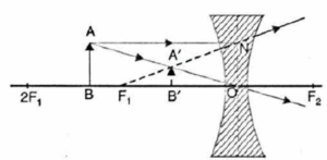
A ray AN parallel to the principal axis, after refraction, appears to come from the focus F1. Another ray from A passes undeviated through the optical centre O. The two rays appear to diverge from the point A’. Thus A’ is the virtual image of A. Hence A’B’ is the complete, virtual, erect and diminished image of the object AB. For all positions of the object the image is always virtual, erect and diminished and is formed between focus F, and the optical centre O. (Fig.)
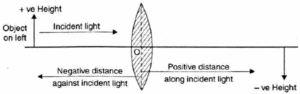
New Cartesian sign convention for refraction of light through spherical lenses :
According to this sign convention: (Ref. fig.)
- All distances are measured from the optical centre of the lens.
- The distances measured in the same direction as the incident light are taken positive.
- The distances measured in the direction opposite to the direction of incident light are taken negative.
- Heights measured upwards and perpendicular to the principal axis are taken positiye,
- Heights measured downwards and perpendicular to the principal axis are taken negative.
Consequences of new Cartesian sign convention:
- The focal length of a convex lens is positive and that of a concave lens is negative,
- Object distance u is always negative.
- The distance of real image is positive and that of virtual image is negative.
- The object height 4 is always positive. Height 2’ of virtual erect image is positive and that of real inverted image is negative.
- The linear magnification, m = h'/h is positive for a virtual image and negative for a real image.
Lens Formula and Magnification :
Lens formula: The lens formula is mathematical relation between the object distance u, image distance v and focal length f of a spherical lens. This relation is: \(\frac{1}{v}-\frac{1}{u}=\frac{1}{f}\)
Where, v = Image distance, u = Object distance, f = Focal length
This formula is applicable to both convex and concave lenses.
Expression for the magnification for (i) convex lens and (ii) concave lens in terms of u and v :
Linear magnification: The linear magnification produced by a lens is defined as
the ratio of the size of the image formed by the lens to the size of the object. It is denoted by m. Thus,
m = \(\frac{size\,of\,image}{size\,of\,object}=\frac{h'}{h}\)
(i) Convex lens: Refer to Fig. for the real image formed by a convex lens.
Here, Δ AOB ~ Δ A'OB'
∴ \(\frac{A'B'}{AB}=\frac{OB'}{OB}\)
According to new Cartesian sign convention,
A’B’ = -h', AB = +h, OB = -u, OB’ = +v
∴ \(\frac{-h'}{+h}=\frac{v}{-u}\) or \(\frac{h'}{h}=\frac{v}{u}\)
∴ Magnification, m = \(\frac{h'}{h}=\frac{v}{u}\)
(ii) Concave lens: Refer to Fig. for the virtual image formed by a concave lens.
Here, Δ AOB ~ Δ A'OB'
∴ \(\frac{A'B'}{AB}=\frac{OB'}{OB}\)
According to new Cartesian sign convention,
A’B’ = +h', AB = +h, OB = -u, OB’ = -v
∴ \(\frac{+h'}{+h}=\frac{-v}{-u}\) or \(\frac{h'}{h}=\frac{v}{u}\)
∴ Magnification, m = \(\frac{h'}{h}=\frac{v}{u}\)
- m is positive for a virtual image formed by a lens.
- m is negative for a real image formed by a lens.
Power of a Lens :
Power of a lens: The power of a lens is the measure of its ability to converge or diverge a parallel beam of light on refraction through it.
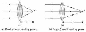
As shown in Fig. a convex lens of shorter focal length bends the light rays more, through large angles, by focusing them closer to the optical centre as compared to convex lens of larger focal length. Hence, smaller the focal length of a lens, more is its ability to bend light rays and greater is its power.
The power of a lens is defined as the reciprocal of its focal length (f) expressed in metres.
Thus,
P = \(\frac{1}{f(in\,m)} = \frac{100}{f(in\,cm)}\)
SI unit of power is dioptre (D). One dioptre is defined as the power of a lens
whose focal length is 1 metre.
Clearly, when f = 1 m
P = 1/1m = 1 m-1 = 1 dioptre (D)
Dioptremeter is used to measure the power of a lens directly on its dial.
- The power of a converging lens is positive because its f is positive.
- The power of diverging lens is negative because its f is negative.
- Focal length will become infinity and its power will become zero i.e., it will no longer act as a lens. It will behave like a plane glass plate.
Power of a lens combination: If a number of lenses of powers P1, P2, P3, … are placed in contact with each other, then the net power (P) of the combination is equal to the algebraic sum of their individual powers. Thus, P = P1 + P2 + P3 +…