
Notes
|
Topics to be learn :
|
Introduction :
Magnet and magnetism: Magnets are substances that possess the ability to attract small pieces of iron, nickel, cobalt, and other metals; this ability to attract is known as magnetism.
- Danish physicist H.C. Oersted was the first to demonstrate in 1820 that a current carrying conductor produces a magnetic field around it.

Natural magnets: Natural magnets are piece of lodestone, which is a black iron ore (Fe3O4) called magnetite.
Artificial magnets: Pieces of iron and other magnetic materials can be made to acquire the properties of natural magnets. Such magnets are called artificial magnets.
- The most common shapes of the artificial magnets are bar magnet, horse shoe magnet and magnetic needle, as shown in Fig.
Magnetic poles: Magnetic poles are the concentrated areas of magnetic strength that are located close to the ends of a magnet.
- The end of a freely suspended magnet which points towards north is called the north seeking or north pole while its end pointing towards south is called south seeking or south pole.
Law of magnetic poles: It states that like poles repel while unlike poles of magnets attract each other. Thus, two N-poles repels, two S-poles repel while N-pole attracts S-pole.
- Repulsion is the surer test of magnetism.
Some basic properties of magnets :
- Attractive property: A magnet attracts small pieces of iron, cobalt, nickel, etc.
- Directive property: A freely suspended magnet aligns itself nearly in the north-south direction.
- Law of magnetic poles: Like magnetic poles repel and unlike magnetic poles attract each other.
- Magngtic poles exist in pairs: If we break a magnet into two pieces, we always get two small dipole magnets. It is not possible to obtain an isolated N-pole or S-pole.
Uses of magnets:
- Magnets are used in radio and stereo speakers.
- They are used in almirah and refrigerator doors to snap them closed.
- They are used in video and audio cassette tapes, on the hard discs and floppies for computers.
- In children’s toys.
- In medicine, the magnetic resonance imaging (MRI) scanners expose the inner parts of the patient’s body for detailed examination by doctors.
Magnetic field and field lines :
Magnetic field: The region around a magnet within which its influence can be experienced is called its magnetic field. A magnet brought in the magnetic field of another magnet will experience a force of attraction or repulsion.
Magnetic lines of force: A magnetic line of force may be defined as the curve the tangent to which at any point gives the direction of the magnetic field at that point. It may also be defined that the path along with a free north pole tends to move.
- Magnetic poles always exist in pairs. So magnetic field lines run from N-pole to S-pole outside magnet and from S-pole to N-pole inside the magnet, forming endless closed loops.
- No two magnetic lines of force can intersect each other, because if two magnetic lines of force intersect, then there will be two tangents and hence two directions of the magnetic field at the point of intersection. This is not possible.
Properties of lines of force:
- These are closed curves which start in air from the N-pole and end at the S-pole and then return to the N-pole through the interior of the magnet.
- No two magnetic lines of force can intersect each other.
- They start from and end on the surface of the magnet normally.
- The lines of force have a tendency to contract lengthwise and expand sidewise. This explains attraction between unlike poles and repulsion between like poles.
- The relative closeness of the lines of force gives a measure of the strength of the magnetic field which is maximum at the poles.
Methods of plotting lines of force: The following two methods are used for drawing lines of force of a bar magnet:
- Iron-filings method.
- Compass needle method.
(i) Iron-filings method : Iron filings near the bar magnet align themselves along the field lines. The lines along which the iron filings align themselves represent magnetic field lines.

The magnet exerts a force on the iron filings of the surrounding region. This force arranges the iron filings along definite lines extending from one end of the magnet to the other. The region surrounding a magnet, in which the force of the magnet can be detected, is said to have a magnetic field. The lines along which the iron filings align themselves represent magnetic field lines.
(ii) Compass needle method : The magnetic field of a magnet can be traced with the help of a magnetic compass needle. The ends of the compass needle point approximately towards north and south directions. The end pointing towards north is called north pole and that pointing towards south is called south pole.
Inside the magnet, the direction of field lines is from its south pole to its north pole. Thus the magnetic field lines are closed curves.
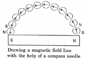
Magnetic field line : A magnetic field line may be defined as the path along which a unit north pole tends to move. The direction of magnetic field is determined by placing a small compass needle. The direction of deflection of N-pole of the compass needle gives the direction of the magnetic field at that point.
Magnetic field due to a current-carrying conductor :
Hans Christian Oersted is the scientist who first established the connection between electricity and magnetism.
Magnetic field of current : A current carrying conductor produces magnetic field around it. This is called magnetic field of current.
- The direction of magnetic field produced by a current carrying conductor depends on the direction of current through it.
Magnetic field due to a current through a straight conductor :
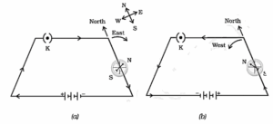
- When the direction of current through the straight wire is reversed, the direction of magnetic field lines also gets reversed as can be seen by the deflection in the compass needle.
- Magnetic needle brought close to a straight current carrying wire aligns itself perpendicular to the wire, reversing the direction of current reverses the direction of deflection. This shows that the current carrying wire is associated with a magnetic field.
- The magnitude of the magnetic field increases as the current through the wire increases.
- The magnitude of the magnetic field produced by a given current decreases as the distance from it increases.
- The concentric circles representing the field lines around a current carrying straight wire become larger and larger as we move away from the wire.
The direction of the magnetic field produced by a current carrying straight conductor can be obtained by using any of the following two rules:
- Right hand thumb rule
- Maxwell’s corkscrew rule:
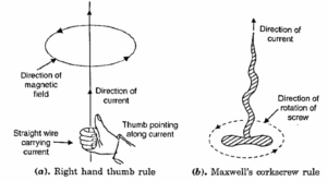
(i) Right hand thumb rule: If the current carrying conductor is held in the right hand such that the thumb points in the direction of the current, then the direction of the curl of the fingers will give the direction of the magnetic field, as shown in Fig.(a).
(ii) Maxwell’s corkscrew rule: If a right handed screw be rotated along the wire so that it advances in the direction of current, then the direction in which the screw rotates gives the direction of the magnetic field, as shown in Fig. 13.9 (b).
Factors on which the magnetic field produced by a straight current carrying conductor depends:
(i) If we increase the current in the conductor, the deflection of the compass needle increases. This shows that, the magnitude of the magnetic field produced at a given point is directly proportional to the current passing through the wire. That is,
B ∝ I
- As B ∝ I, the strength of magnetic field increases on increasing the current through the conductor.
- On changing the direction of flow of current, the direction of the magnetic lines of force is reversed.
(ii) For a given current, if we move the compass needle away from the wire, its deflection decreases. This shows that the magnitude of the magnetic field produced by a given current in the wire is inversely proportional to the distance from the wire. That is,
B ∝ 1/r
Magnetic field due to a current through a circular loop :
- Figure shows the magnetic field lines of a circular wire carrying a current. The lines of force near the wire are almost concentric circles. As we move towards the centre of loop, the concentric circles become larger and larger. Near the centre of the loop, the arcs of these big circles appear as parallel straight lines.
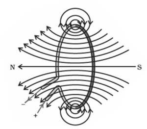
- Thus the magnetic field is almost uniform at the centre of the loop. By applying right hand rule, we can see that the magnetic field lines due to all sections of the wire are in the same direction within the loop. That is why the field is stronger at the centre or near the circumference of the loop.
Factors on which the magnetic field produced at the centre of circular coil carrying coil depends on :
- It is inversely proportional to the radius of the coil. That is,
B ∝ 1/r
- It is directly proportional to the number of turns n of the coil. As the direction of current in each circular turn is same, the fields due to the various turns get added up. That is,
B ∝ n
- It is directly proportional to the strength of current passing through the coil. That is,
B ∝ I
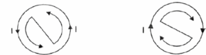
Clock rule: The polarity of any face of circular current loop can be determined by using clock rule, as shown in Fig. If the current round any face of the loop flows in anticlockwise direction, it behaves like a north pole. If the current flows in the clockwise direction, the face behaves like a south pole.
Magnetic field due to a current in a solenoid :
Solenoid:
- A long cylindrical coil of insulated copper wire of large number of circular turns is called a solenoid.
- When an electric current is passed through a solenoid, it produces a magnetic field around it. Its magnetic field pattern is shown in Fig. (a).
- When a current is passed through the solenoid, the current in each circular loop has the same direction, their magnetic effects get added up producing a strong magnetic field.
- Inside the solenoid, the magnetic field is almost uniform and parallel to the axis of the solenoid.

The magnetic field produced by a solenoid is very much similar to that of a bar magnet. Like a bar magnet, one end of the solenoid has N-polarity while the other end has S-polarity. The polarity of any end (face) of the coil can be determined by using clock rule. For all practical purposes, the magnetic field of a solenoid and that of a bar magnet can be taken identical.
Factors on which the strength of the magnetic field produced by a current carrying solenoid depends:
- Number of turns in the solenoid: The larger the number of turns in the solenoid, stronger is the magnetic field produced. The magnetic effects of all circular loops, being in the same direction, get added up, producing a very strong magnetic field.
- Strength of the current: The larger the current passed through the solenoid, stronger is the magnetic field produced.
- Nature of the core material: By winding the coil over a soft iron cylinder, called core, the magnetic field can be increased several thousands times.
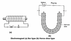
Electromagnet:
A soft iron core placed inside a solenoid behaves like a powerful magnet when a current is passed through the solenoid. This device is called an electromagnet.
When the current is switched off, the iron core loses its magnetism and so it is no longer an electromagnet. Thus, electromagnets are temporary magnets. See Fig.
Factors on which the strength of an electromagnet depends:
- Number of turns in the coil: The larger the number of turns in the coil, greater is the strength of the electromagnet.
- Strength of the current: The larger the current passed through the solenoid, more powerful is the electromagnet.
- Nature of the core material: The core of the magnetic material like soft iron increases the strength of the electromagnet.
Characteristics of Electromagnet :
- It is a temporary magnet. It shows magnetism only as long as the current is passing through its coil.
- It can produce very strong magnetic field.
- The strength of an electromagnet can be easily varied by changing the strength of current or number of turns in the coil.
- The polarity of an electromagnet can be reversed by sending the current in reverse
Uses of electromagnets:
- Electromagnets are used in factories and cranes to lift heavy iron ingots and steel scraps from one place to another.
- They are used in hospitals to remove iron splinters from the eyes of the patients.
- They are used in electric bells, relays, electric switches, etc.
Temporary and permanent magnets :
(i) Temporary magnets: The magnets which show their magnetism only in the presence of a magnetising field (or current) are called temporary magnets. For example, a soft iron core remains magnet only as long as the current passes through the solenoid. So, it is a temporary magnet.
(ii) Permanent magnets: The magnets which retain their magnetism even after the magnetising field (or current) has been removed are called permanent magnets. For example, a steel core remains a magnet even if electric current through the solenoid is switched off.
Permanent magnets are usually made of following materials:
- Carbon steel, chromium steel, cobalt and tungsten steel.
- Nipermag and alnico are two important alloys whose permanent magnets are used in industry. Nipermag is an alloy of iron, nickel, aluminium and titanium while alnico is an aluminium-nickel-cobalt alloy of iron.
- Magnetism in steel or alnico stays for a longer duration.
Characteristics of permanent magnet :
- It retains magnetism for a long time even after the removal of the magnetising field (or current).
- It produces a much weaker field than an electromagnet.
- Its strength cannot be changed.
- The polarity of a permanent magnet cannot be changed.
Uses of permanent magnets:
- In microphones, loudspeakers and electric clocks.
- In devices like ammeters, voltmeters and speedometers.
- In electric generators and motors.
- On video and audio cassette tapes.
Advantages of electromagnet over a permanent magnet:
- An electromagnet can produce a very strong magnetic field.
- The strength of the magnetic field of an electromagnet can be increased / decreased by increasing/decreasing the strength of current or the number of turns in the solenoid.
- The polarity of an electromagnet can be reversed by sending the current in the reverse direction.
Force on a current-carrying conductor in a magnetic field :
We know that an electric current flowing through a conductor produces a magnetic field. This field exerts a force on a magnet placed near the conductor. In accordance with Newton’s Third law, the magnet must also exert an equal and opposite force on the current carrying conductor. Thus a magnetic field exerts a force on a current-carrying conductor.
Such a force was first suggested and demonstrated experimentally by French Scientist Andre Marie Ampere in 1820.
Factors on which the force as a current carrying conductor in a magnetic field depends:
(i) Magnitude and direction of current in the conductor. (ii) Magnitude and direction of the magnetic field. (iii) Length of the conductor.
- When the current-carrying conductor is held perpendicular to the direction of the magnetic field, the force exerted on it is maximum.
- When the current-carrying conductor is held parallel to the direction of the magnetic field, the force exerted on it is minimum or zero.
Fleming’s left hand rule: Stretch the forefinger, the central finger and the thumb of the left hand mutually perpendicular to each other. If the forefinger points in the direction of the magnetic field, the central finger in the direction of current, then the thumb points in the direction of force on the conductor.

The direction of earth’s magnetic field is from geographical south to geographical north. According to Fleming’s left hand rule, the current carrying straight conductor placed in east-west direction will be deflected downwards.
- On reversing the direction, the conductor is deflected in the upward direction.
- If the magnitude of current is doubled, it will result in doubling the magnitude of the force.
Factors on which the force experienced by a current carrying conductor placed in a magnetic field depends:
- Strength of magnetic field: F ∝ B
- Strength of electric current: F ∝ I
- Length of the conductor: F ∝ L
- Direction between current and magnetic field: F ∝ sin θ
- Magnitude of the magnetic force is F = BIL sin θ
- When the current carrying conductor is perpendicular to the magnetic field, force experienced is maximum. Fmax = BIL sin 90° = BIL
Use of Magnetism in medicine :
The magnetic field inside the body forms the basis of obtaining the images of different body parts. This is done using a technique called Magnetic Resonance Imaging (MRI). Analysis of these images helps in medical diagnosis. Magnetism has, thus, got important uses in medicine.
Domestic electric circuits :
Electricity supplied to our homes :
The electricity supplied to our homes is:
- Type of current : Alternating Current (AC),
- Voltage of electricity supplied : 225V,
- Frequency of current supplied : 50 Hz
The mains bring to our homes two supplies with different current ratings:
- Different electric appliances have different power ratings. So they draw different currents when connected to the mains. Some appliances need smaller currents, while some others need heavy currents. So, we need two lines of current ratings 5 A and 15 A.
- The 5 A line is called domestic line or light line. It is used for electric bulbs, fluorescent tubes and fans. The 15 A line is called power line. It is used for heaters, geysers, airconditioners, irons, etc.
Domestic wiring: A schematic diagram for household electric installation is shown in Fig.

The main features are:
- The electric supply from the mains is delivered to our homes using a three core cable. One wire with red insulation cover is called live wire which brings in the current. The second wire with black insulation is called neutral wire which provides the return path for the current. The third wire is the earth wire. The potential difference between live and neutral wires is 220 volts in India.
- The earth wire is either thick uncovered copper wire or a copper wire with green insulation. It is usually connected to a metal plate deep in the earth near the house. It is used as a safety measure which does not affect the supply in any way.
- The wires from the supply line pass into the watt-hour-meter through a main fuse. Then through a main switch, these wires enter a distribution box.
- From the distribution box, several independent distribution circuits are drawn which go into different parts of the house. The live wire of each circuit passes through a separate fuse so that during short circuiting, only the electricity to that part of the house is cut off and others are not affected.
- In any part of the house, all appliances are connected in parallel to each other across the live and neutral wires. This ensures full voltage across each appliance from the mains. Each appliance is provided with a separate switch in its live wire for its operation.
- Two separate circuits are used, one of 15 A for appliances with higher power ratings and the other of 5 A rating for bulbs, etc.
- The main switch is used to switch off the main supply required at the time of repairing or any other emergency.
Advantages of connecting different electrical appliances in parallel :
In a household electric circuit, different appliances are connected in parallel to one another due to the following reasons:
- The appliances can be operated independently. If one appliance is switched off, others remain unaffected.
- Each appliance gets the same constant voltage.
- If one line is overloaded, the fuse in this circuit only will be blown off. Other distribution lines are protected.
- There is a constant potential difference across each line.
- If more lines are added in the circuit, it makes no difference to the other lines as p.d. is maintained at a constant value.
Short circuiting and overloading in an electric supply :
- Short circuiting: If due to defective or damaged wiring, the live and neutral wires come in direct contact, the resistance of the circuit becomes almost zero and an extremely large current flows through the circuit. This is called short circuiting. It results in heating the line wires and may damage the appliance. It may produce spark at the place of short circuit and cause fire. Short circuiting can be prevented by using an electric fuse in live wire.
- Overloading: When a large number of high power appliances are switched on simultaneously, they draw extremely large current from the mains. If the current drawn from the mains exceeds the safety limit (5 A for domestic line and 15 A for power line), then this is known as overloading. As a result of overloading, the wires get over heated and the appliances may get damaged. This can be avoided by using an electric fuse in live wire.
Electric fuse: It is a safety device used to protect an electric circuit from overloading or short circuiting. It is a small piece of wire of a material having low melting point and high resistance. A fuse wire is made of pure tin or of an alloy of copper and tin.
Role of fuse in series with any electrical appliance in an electric circuit :
- The working of an electric fuse is based on the heating effect of current.
- A fuse wire has low melting point and high resistance. It is connected in series with the live wire.
- When an excessive current flows through it, the wire melts and the circuit is broken.
- The electric current stops flowing immediately. Electric appliances are thus prevented from getting damaged.
Types of electric fuse :
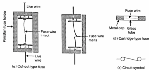
Two types of electric fuse commonly used : (i) cut-out type (ii) cartridge type
Electric fuses commonly used in domestic circuits are of cut-out type shown in Fig. (a) while those used in electric appliances such as TV, computers, music systems etc., are of cartridge type shown in Fig. (b). The circuit symbol of an electric fuse is shown in Fig. (c).
Fuse rating:
- The maximum safe current allowed to flow through a fuse before it melts is called fuse rating.
- The thickness and length of fuse wire depend on the fuse rating.
- In a live wire, we should use a fuse of rating slightly higher than the maximum current that can flow through it.
- A fuse of 5 A rating is used in line meant for bulbs, fans, etc. A fuse of 15 A rating is used in line required to feed appliances of power 1000 watt or more.
- A fuse of proper rating should be used in a circuit. If a fuse of higher rating is used, it will not blow and will not protect the circuit. If a fuse of lower rating is used, it will blow before the circuit is fully loaded.
Earthing: Earthing of an electrical appliance means connecting the metallic body
of the high powered appliance (electric iron, toaster, refrigerator, oven, etc.) to the earth through the earth wire of the domestic circuit. The earth wire has green insulation cover and is connected to a metal plate deep in the earth near the houses and hence it is at zero potential.
Function and importance of earthing: If, by chance, the live wire touches the
metallic body of the electrical appliance, its current flows to the earth through the earth wire, which provides a low resistance conducting path for the current. Thus, the earth wire (or earthing) is used as a safety measure which ensures any leakage of current to the metallic body of the appliance keeps its potential equal to that of the earth (zero volt) and the user may not get a severe electric shock.
Safety :
- It is not advisable to handle domestic electrical circuit with wet hands. Wet hands are good conductors of electricity. Any leakage of current from the domestic circuit will give us an electric shock while handling it.
- Electricians wear rubber shoes or rubber hand gloves while working. Rubber is a good electrical insulator. It does not allow the current to pass through electrician’s body and saves from electric shocks, if accidentally he touches the live wire.